Polarization Mismatch Loss Calculator
Dr. Phillip M. Feldman
1. Background
A plane electromagnetic wave propagating in free space is fully characterized by flux density
(Watts/square meter) and three polarization parameters: axial ratio of the polarization
ellipse, tilt angle of the ellipse, and polarization rotation sense (right or left). If the
polarization is linear, the rotation sense is undefined. If the polarization is circular, the
tilt angle is undefined.
A non-array-antenna (or single element of an array antenna) has a specific polarization; this is
the polarization of the wave that the antenna produces in the far field when the terminals are
excited with a sinusoidal voltage. The polarization of an antenna, like gain, is a function of
direction and frequency.
The polarization of the wave that an antenna produces is also the polarization that it receives
most efficiently. If a wave having some other polarization arrives at the antenna, there will be
a polarization mismatch loss; this loss is the ratio of the available power at the antenna
output to the power that would have been available given a polarization-matched wave (having the
same flux density). Polarization mismatch loss is usually expressed in dB. If the arriving wave
has a polarization that is orthogonal to that of the antenna, the polarization mismatch loss is
infinite.
2. Formulas
Consider the general case of a wave with an arbitrary elliptical polarization impinging on an
antenna with an arbitrary elliptical polarization. The polarization mismatch loss in dB—
a non-negative number according to the convention that we follow—is given by the following
equation, which can be found in various sources (e.g.,
http://www.dtic.mil/dtic/tr/fulltext/u2/637134.pdf
where:
r_T is the signed linear (i.e., non-dB) axial ratio of the wave. (The linear axial ratio is the
ratio of the major and minor axes of the polarization ellipse). If a wave is not linearly
polarized, and the electric field vector rotates in a counter-clockwise direction as viewed by
an observer behind the wavefront, the signed linear axial ratio is negative. Otherwise, the
signed linear axial ratio is positive.
r_R is the signed linear axial ratio of the antenna.
β is the angle between the semi-major axes of the two polarization ellipses, or
equivalently, the difference between the two tilt angles, modulo π. Note that this definition
for β follows the convention that, regardless of whether an antenna is actually
transmitting or receiving, the antenna's polarization (including tilt angle) is based on the
antenna operating in transmit mode.
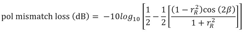
In the case where the wave is linearly polarized, r_T tends to infinity and the above formula
cannot be used. Taking a limit, we obtain
3. Calculator
If a polarization is linear, enter 60 for the dB axial ratio and R for the rotation sense. If
a polarization is circular, enter 0 for the dB axial ratio and 0 for the tilt angle.
Last update: 4 Sept., 2021